|
|
Post by bender88 on Mar 1, 2017 19:06:56 GMT -5
Hello, I'm new here at the HOH, but have been around Homelites since the 60s racing Karts. I have a few unrestored saws, a couple of 500s, a 600, a couple of 700 series, a 1000, some C series, and 2100(s) parts. About the 2100S, I have collected most of the parts to make a complete power-head, new cylinder and piston, however the rotor - flywheel part no 65480 seems nearly impossible to find. I have not even been able to find a picture of one. I'm trying to figure out a plan B, assuming that I will never find a rotor. It looks like I may be able to retrofit back to the C series -2000 internal coil style ignition and matching rotor. Or maybe another rotor, of a different make with the external coil style could be made to work. So I have some questions, and I'd appreciate any help. I could use some pictures of a 2100S rotor, maybe with some basic dimentions, OD and height. I want to compare the keyway - magnets location to the other flywheels. I've been trying to measure the crankshaft - rotor taper angle in various flywheels. Its tricky to measure, but I get a taper of 10 degees which seems to be common in most chainsaw flywheels, I'd like to verify that, if anybody knows.
Thanks, Jim (Bender88)
|
|
|
|
Post by onlyhomelites on Mar 1, 2017 23:13:49 GMT -5
Welcome to HOH Jim! I don't have the info that you need, but chainsawlady is as likely as anyone to have a rotor. If she does have one, I'm sure she'll post a response.
|
|
|
|
Post by sawnami on Mar 2, 2017 8:23:39 GMT -5
I've got a 2000E, 2100AO, and a Super 2100. Any of those a match?
|
|
|
|
Post by bender88 on Mar 2, 2017 12:34:59 GMT -5
Hi sawnami,
The IPLs show that any 2100 or 3100 series would use the rotor I'm looking for. (part no 65480) The 2000 would not, as it uses the XP series style ignition, with internal under the rotor coil.
So its the saws with two piece rotor cover, 2100 and 3100G series, with the external coil mounting to the cylinder, that has the rare rotor.
If you have an extra one, even damaged, I would be interested in buying it, otherwise if you happen to have one of your saws apart, some photos of the rotor would help.
help.
|
|
|
|
Post by sawnami on Mar 2, 2017 14:54:07 GMT -5
Hi sawnami, The IPLs show that any 2100 or 3100 series would use the rotor I'm looking for. (part no 65480) The 2000 would not, as it uses the XP series style ignition, with internal under the rotor coil. So its the saws with two piece rotor cover, 2100 and 3100G series, with the external coil mounting to the cylinder, that has the rare rotor. If you have an extra one, even damaged, I would be interested in buying it, otherwise if you happen to have one of your saws apart, some photos of the rotor would help. help. I'll see if I can get you some pics of the 2100AO. |
|
|
|
Post by vintagesaw on Mar 2, 2017 15:15:51 GMT -5
Call rich at myrtle creek saw shop aka the chainsaw guy
|
|
|
|
Post by bender88 on Mar 2, 2017 18:39:47 GMT -5
Thanks sawnami, and vintagesaw, On the 2100 Rotor get the Phelon casting no, if its not too much trouble. I have an old Phelon co cross reference listing, that shows who used a particular flywheel casting.
I called rich at myrtle creek, he does not have one.
|
|
|
|
Post by lesorubcheek on Mar 2, 2017 20:26:59 GMT -5
Hello and welcome Jim, That is one tough part to find, You're right with all your info, except its a Wico/Prestolite, not a Phelon/Repco. I happen to have one out at the moment, so attached a picture of the back showing the casting number. Looks like the casting number is Y17558. This one unfortunately has a broken fin. I'll probably break the opposite side fin to try to balance it. Dan 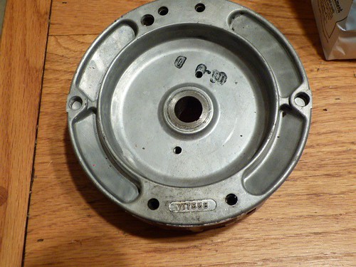 |
|
|
|
Post by sweepleader on Mar 2, 2017 20:44:31 GMT -5
Yes, this is good stuff Jim and all.
Dan, perhaps you were going to already, if so this suggestion if for someone else, yeah, that's it, someone else. :{)
I would be inclined to grind both areas with missing fins down flush with the surface of the wheel, to get the remaining material on each side to match as best I could.
|
|
|
|
Post by lesorubcheek on Mar 2, 2017 22:08:47 GMT -5
Right on.... Dremel to the rescue. Wish I had a contraption to try to balance flywheels. This isn't the first flywheel sittin' around with a broken fin. Thought about trying to rig something like used for balancing RC plane props. The magnets aren't nearly strong enough to support the weight of a flywheel though. It would need some very strong magnets to support that much weight. Even with balanced weight, I still worry about the uneven airflow turbulence. Go ahead and say it.... way overthinking it. I know, I know... Wouldn't be any problem if you could find things like this to replace it.
Dan
|
|
|
|
Post by sawnami on Mar 2, 2017 23:43:09 GMT -5
Thanks sawnami, and vintagesaw, On the 2100 Rotor get the Phelon casting no, if its not too much trouble. I have an old Phelon co cross reference listing, that shows who used a particular flywheel casting. I called rich at myrtle creek, he does not have one. Thanks for the information Dan! bender88, are you good to go with Dan's information then? |
|
|
|
Post by sweepleader on Mar 3, 2017 7:46:23 GMT -5
Two methods that may not be workable in this case but are used for balancing that I have used in the past:
1. Unsealed ball bearings with just light oil lube for support. Mount wheel on the shaft. It could be overhung, on the end of the shaft if the bearings were properly supported.
2. If the wheel could be mounted in the middle of the shaft, it could be supported by knife edges. Those edges really don't have to be knife edges but they must be narrow and smooth and level.
In both of these the wheel could be centered axially on the shaft with cones that closely fit the shaft and are slid into the wheel bore from each side. They can be held in place with a nut or whatever works.
Please describe the magnet method...
|
|
|
|
Post by sawnami on Mar 3, 2017 8:13:26 GMT -5
Two methods that may not be workable in this case but are used for balancing that I have used in the past: 1. Unsealed ball bearings with just light oil lube for support. Mount wheel on the shaft. It could be overhung, on the end of the shaft if the bearings were properly supported. 2. If the wheel could be mounted in the middle of the shaft, it could be supported by knife edges. Those edges really don't have to be knife edges but they must be narrow and smooth and level. In both of these the wheel could be centered axially on the shaft with cones that closely fit the shaft and are slid into the wheel bore from each side. They can be held in place with a nut or whatever works. Please describe the magnet method... Sounds like how I balance my motorcycle tires. You need the PicoScope with the 3-channel vibration accelerometer from my work. It measures and graphs in milli-G units. |
|
|
|
Post by lesorubcheek on Mar 3, 2017 16:33:18 GMT -5
Please describe the magnet method... Here's a stock photo... didn't feel like transferring another pic from the camera.  Magnets on either side of the support rod hold it with zero friction. You can imagine how strong the magnets would need to be to support the weight of a flywheel! Dan |
|
|
|
Post by Supercharged86 on Mar 3, 2017 22:34:28 GMT -5
....You need the PicoScope with the 3-channel vibration accelerometer from my work. It measures and graphs in milli-G units. Are you sure you don't need a "Flux-Capacitor" for this job? He He He. Doc Brown says it will only work with the Flux-Capacitor. Sorry guys, couldn't resist.  |
|
|
|
Post by bender88 on Mar 6, 2017 19:20:41 GMT -5
Thanks everybody, Dan thanks, for the photo, take one of the fin side if the saw is still apart, it helps to recognize one when I see it. One thing I learned is that the Phelon basic "cast number" refers to the complete magneto assembly, coil, points and all. A suffix stamp IDs it farther, but the ROTOR, has another Phelon part no.
I've also been wondering about the balancing of the engines and flywheels. Are the engines and flywheels balanced separately and neutral? I have a lot of the F2430 flywheels, but every one has a different drilled hole balancing pattern.
I'm also trying to measure the FW and - shaft tapers. I put different size steel balls in the taper, then measure their separation, and with a little trig I get 10 degrees on most FWs. It not easy takes a good surface plate and good dial indicators. I'm studying this because I'd like to be able to modify or make a flywheel, for any engine.
Jim
|
|
|
|
Post by sweepleader on Mar 6, 2017 20:16:09 GMT -5
That is an interesting idea, making your own. I would have to guess that the magnets would preclude actual casting but modifying something else to fit seems possible...
The individual castings have different internal void patterns, gas bubbles and shrinkage voids. Look at broken surfaces of any casting and you will see them. Their dispersion in the casting will determine to a great extent the balance of the part, each one needing its own pattern of drillings to correct.
I really have no idea what Homelite did regarding balancing to a particular engine, I doubt that happened as it would add significantly to production time. On the other hand, flywheels may not be balanced in them selves but rather balanced to a standard crank which would likely throw them off if mounted on a straight shaft. I know there are a lot of automotive engine parts that look round but are not balanced round. The engine in my old truck comes to mind, a 400 cid Chev with unbalanced harmonic damper and flywheel. The crankcase is not big enough to balance the crank internally so they do it externally with those add on parts.
Also, the connecting rod does not present a "concentric" weight to the engine's rotating mass so balancing becomes a guessing game regarding how much at what speed. I do not know the specifics of that deal.
I bet sawnami with his "PicoScope with the 3-channel vibration accelerometer" could offer help.
Maybe superchared86 can find us a flux capacitor, eh?
|
|