|
|
Post by lesorubcheek on Jun 14, 2012 20:09:04 GMT -5
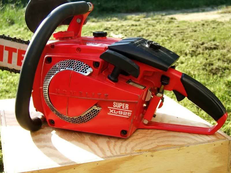
Decided I need to quit dragging around with this 925 resto that's been waiting for a while now. Big thanks to Dewayne for the last parts it was needing!!! Started out by stripping it down and cleaning out the fuel tank. It was gummed up with old fuel and a melted rubber fuel line. After cleaning her out, I removed the alignment pin and using some 400 grit emery cloth with light oil, gently polished the mating halves of the tank. 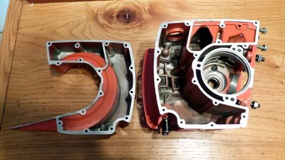 Internals were in pretty good shape. Looks like many 925s, even with the electronic ignitions, used the same crank as the point types. I've came across more than one this way. Seems the later ones may have finally changed to a crank without lobes for points. Here's a pic of the two different cranks. Top is off a 955 and bottom is from this 925. The original crank is in great shape, so it'll go back in. 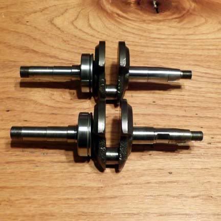 Tomorrow I'll try to get started on putting some of it together. Dan |
|
|
|
Post by Brian VT on Jun 14, 2012 20:36:34 GMT -5
I'll be following this with interest. I have a 925 that's been awaiting my attention for @ 2 yrs.
|
|
|
|
Post by tribulation138 on Jun 15, 2012 6:15:14 GMT -5
are you rebuilding the saw? or a full restore like paint etc??
|
|
|
|
Post by lesorubcheek on Jun 15, 2012 19:36:23 GMT -5
Very good point. Not really planning a full restoration with repainting, just rebuilding to get her running again. This one's in fairly nice cosmetic shape anyway. So, renamed the title to "925 rebuild". Getting the tank cover back on today. Here's the piece-parts. Note 6 short screws, 8 long and 1 intermediate length. 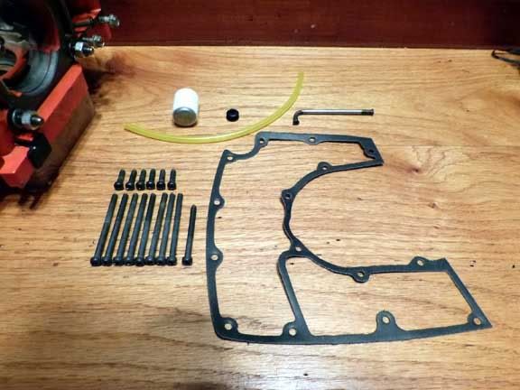 First, its a lot easier to get the rubber grommet and line in place with the tank split. The grommet just needs a little persuasion from a small screwdriver. Here's the grommet in place as seen from the outside. 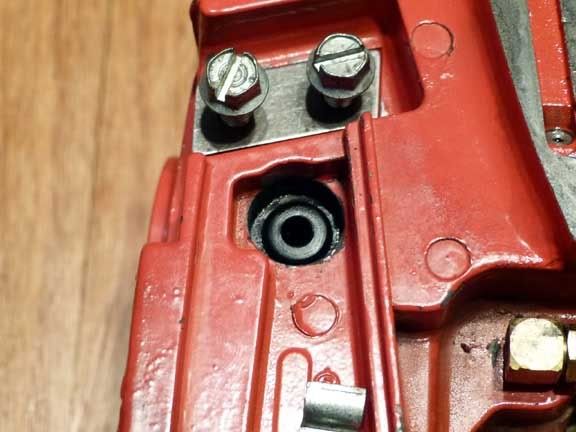 ...And from the inside. 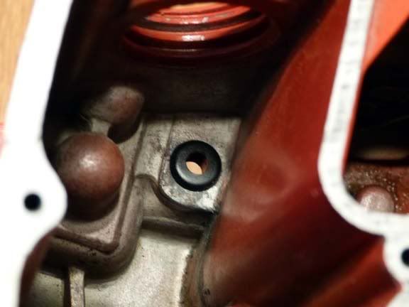 Slide the new fuel line through the grommet, attach the filter on the inside. 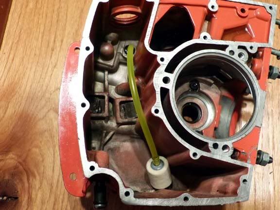 ... and attach the 90 degree tube on the outside and press it through the grommet. No need to tighten up the retainer clip yet since the second half of fuel line will be attached later. 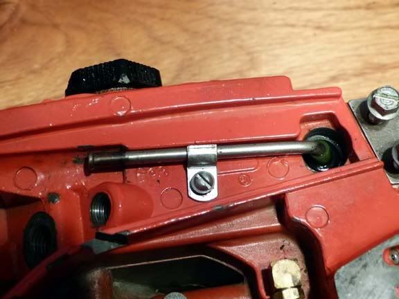 Reinstalled the dowel pin for the back plate which was removed when resurfacing. About all 925s I've seen seem to have only one pin and its on the top, even though there's a hole drilled on the bottom section also. For some reason there's usually two on the 955s. Not sure why the change. One works fine. Gasket is in place, tank halves joined and bolts in place. The odd sized slightly shorter screw goes in the upper-right-most hole. 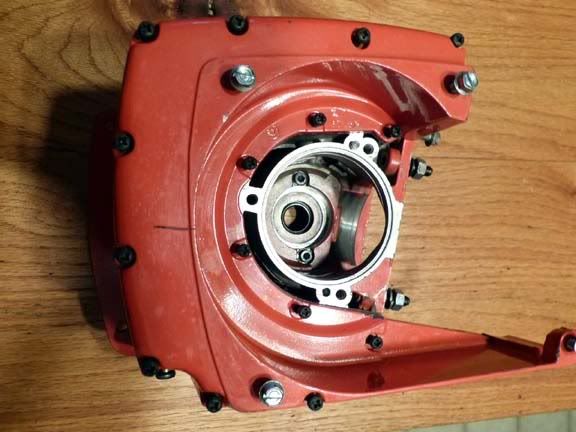 Finally, torqued bolts to 30 in-lbs. They're 8-32 and may take a little more, but think they'll be plenty tight. Had to secure the case by the bar studs (nuts on 'em to not mess up the threads) in a vise to get good enough grip to tighten them properly. I use blue loctite on just about everything, but left it off of these in case they ever need removal or tightening in the future. 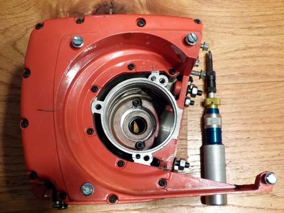 At this rate, its gonna take a month to finish, but really wanted to capture all the details along the way. Dan |
|
|
|
Post by Brian VT on Jun 15, 2012 20:18:29 GMT -5
...really wanted to capture all the details along the way. Dan Very much appreciated. I know it slows you down quite a bit. |
|
|
|
Post by lesorubcheek on Jun 17, 2012 20:04:10 GMT -5
Crank bearings are in good shape so not changing them. Make sure the circlip is in place on the end of the crank to retain the bearing or the crank won't have anything to control lateral movement. There's two T-25 bolts and special thickness washers that retain the bearing within the crankcase. The bearing has a slot cut around it that the washers fit into to keep it in place. 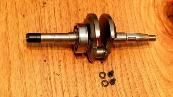 Its important to only press on the outer shell of the bearing when installing. Homelite made some special tools for this. I have these for the little EZs, but unfortunately not for a bigger saws. 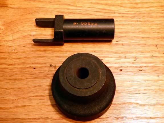 So, I'll use a punch instead, and heating the case doesn't hurt to expand it and make the bearing an easier fit. 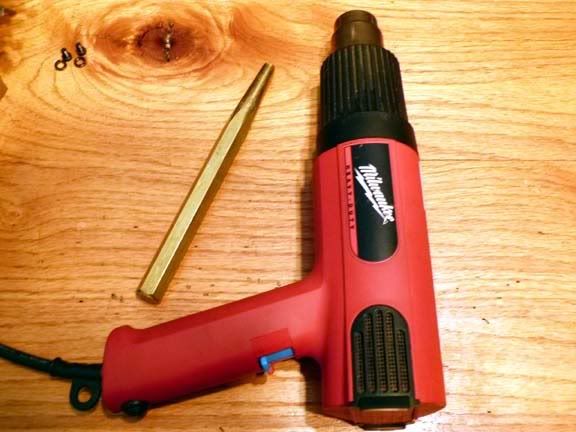 I may be sorry later, but the crank seals both looked good, so decided not to change them. I oiled it well with two stroke oil and then to keep the heat gun from damaging the seal, I covered with some paper. 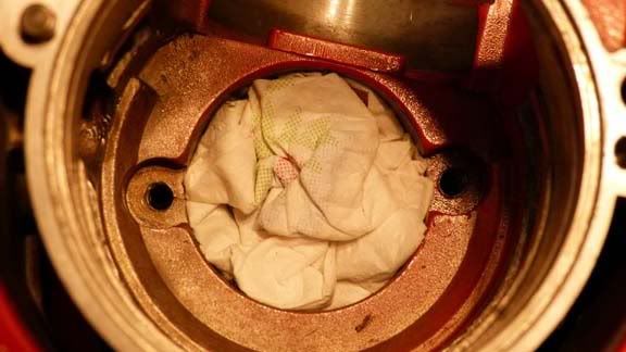 And after a little persuasion, the crank is in place with retainers. 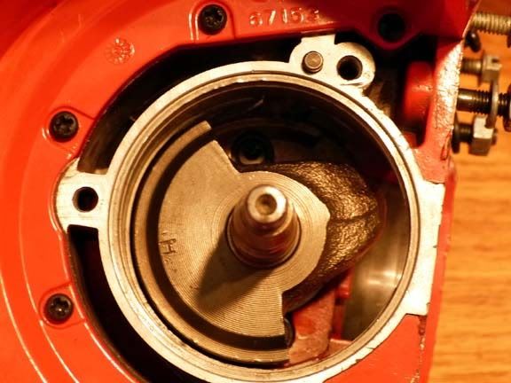 Now time for the connecting rod, bearings and piston. 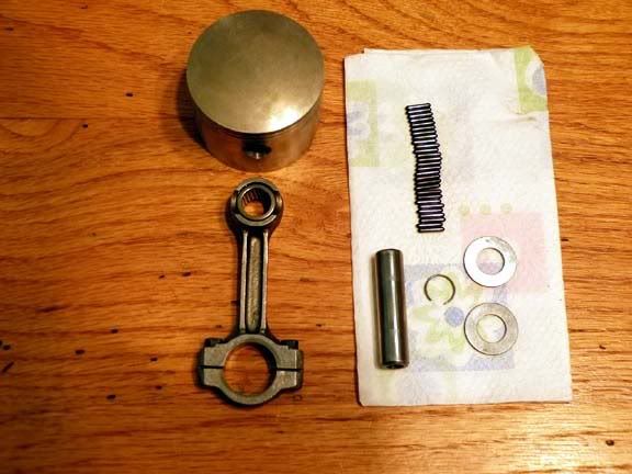 The piston has a few scratches, but nothing major, so going to try to get more life from it. Its important to make sure the alignment pins for the rings are on the intake side when the piston gets installed, 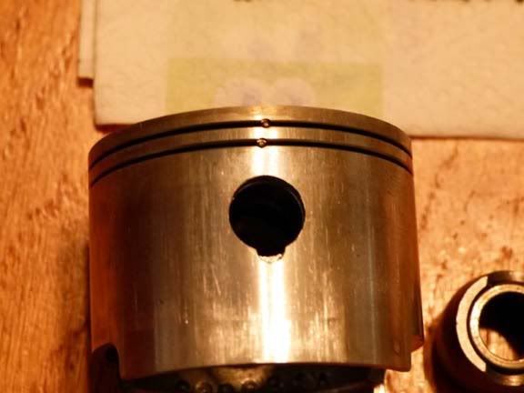 It can be easier juggling the rod alone sometimes when installing with the loose bearings, but since the 925 has these two thrust washers that sandwich on either side on the top to prevent lateral movement, I think its a little easier to go ahead and assemble the rod to the piston first. The pin has a closed end and an open end. Make sure the closed end goes on the exhaust side. Don't forget the circlip after installing the pin! 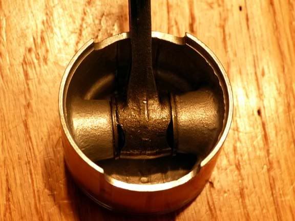 When installing the rod, it never hurts to put a mark to make sure you remember which way the lower end fits together. 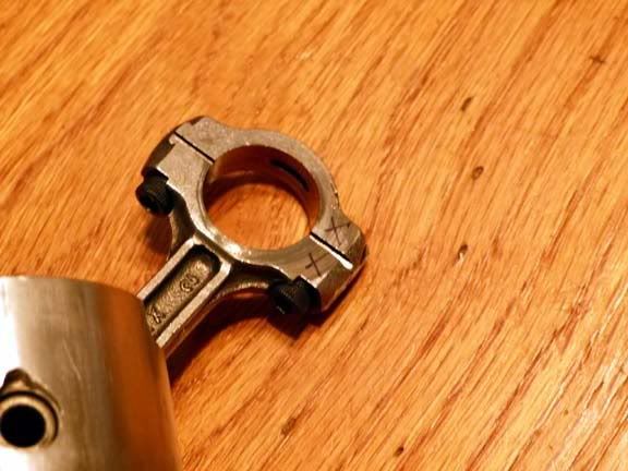 Here's a little trick that can prevent alot of aggravation. Cut a piece of wire (I used #12 electrical wire) that'll fit snugly in the bolt hole in the rod base. Bend it around like this. It'll hold the bottom section of the rod with the roller bearings on it. 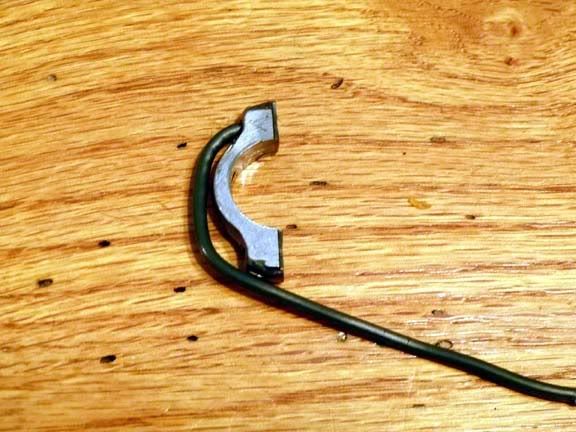 I use wheel bearing grease to hold the roller bearings in place. Book says grease or beeswax. 14 rollers on the top and 14 on the bottom. 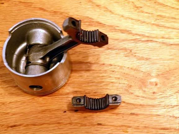 Use the wire trick to hold the lower section of the rod in place. 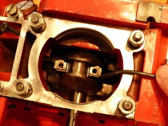 Lower the upper rod making sure not to bump the rollers and make them fall off. Start one of the bolts, remove the wire, and then start the other one. Tighten the rod cap bolts and you're done. 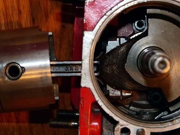 Now its time to drop on the cylinder. I decided to use new rings even though the old rings still had pretty good compression. 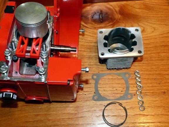 Gasket in place, rings installed and oiled, and the handy helper that comes in the Bailey's piston ring compressor set. 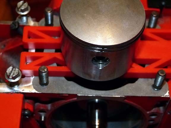 Squeeze the rings, and its an easy job putting on the cylinder. Some argue the point, but I always oil the piston and cylinder well with 2 stroke oil before assembling. 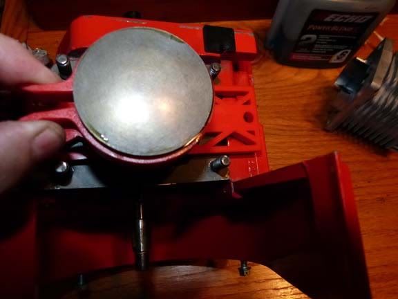 Lock washers and nuts and tighten them down. Its easier to just start each nut (not tighten down) since the two on the exhaust side are easier if the cylinder is lifted up a bit and not sitting on the gasket. 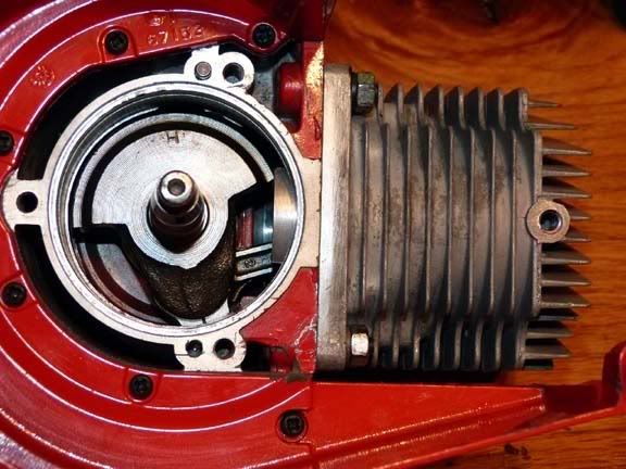 |
|
|
|
Post by lesorubcheek on Jun 17, 2012 20:27:36 GMT -5
Now for the ignition. Homelite used a single piece electronic system on the later 925s that can be retrofitted to any of the older ones. 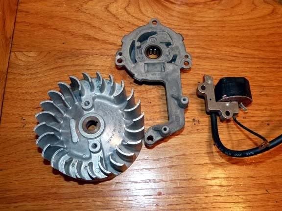 I personally like the 3 piece original better, if for no other reason because its unique. Here's the parts. 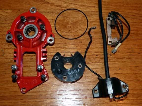 First attach the module with 3 bolts. There's a wire that connects on the tab marked "TRANS". Notice how it intertwines in and around the tabs on the cover. 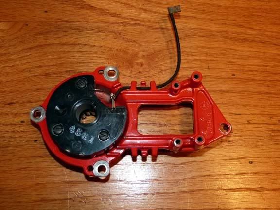 Next, the generator. It has three wires. One has a round lug and is for ground. It attaches on one of the mounting lugs. The shorter wire goes to the trigger module and attaches on the tab labeled "GEN", The third wire has a band on the end and will attach later to the kill switch. 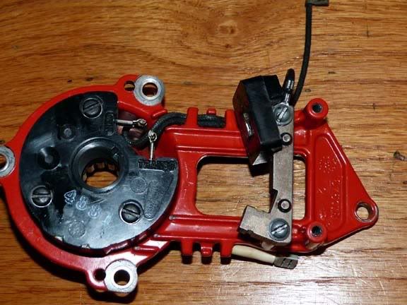 Finally, its time for the transformer. It also has a grounding lug. There's a single connector and it gets the wire that comes from the trigger module. 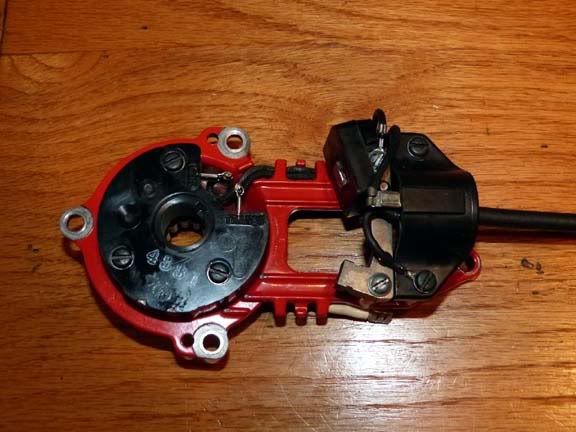 Its recommended to seal the connections on the module to prevent possible problems with moisture. Was out of silicon, so I used some Threebond. It should seal it up well enough. 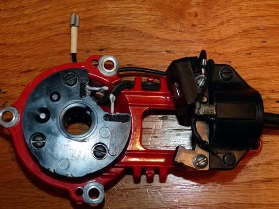 An o-ring seals the case cover to the case. I oiled the bearing and the seal well here too before installing. 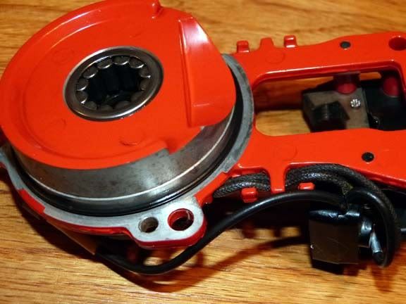 If you have one of the crank thread cover protectors, use it now to prevent possible damage to the seal when you slide it over the end of the crank. If you don't have one, tape works fine too. Lower the cover in place, and attach the three bolts on the case and locking tab and fourth bolt on the cylinder. Bend the locking tab to keep the bolt from working loose. 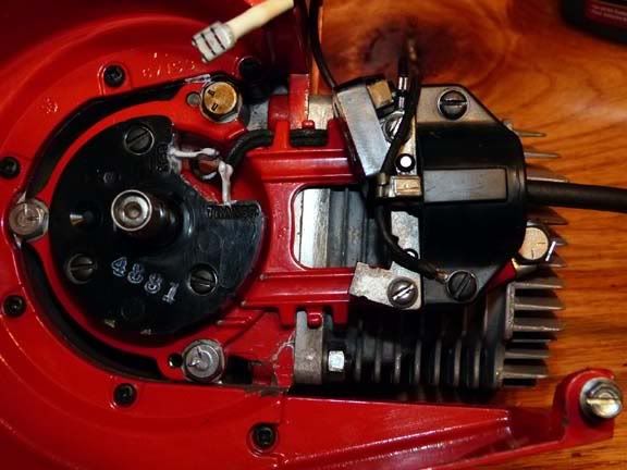 Couldn't stand waiting to see if the ignition would work, so I went ahead and put on the flywheel. Spun it by hand and nothing....  . Then I decided to go ahead and fit the pull starter. Thankfully, all is well as it produced a very nice spark. Most point type ignitions I can get a fine spark with a hand spin. Haven't experimented to see, but just one case where this 3-piece setup needed a little faster than a hand spin to get a spark. |
|
|
|
Post by Brian VT on Jun 17, 2012 21:55:53 GMT -5
Great stuff. Thanks for all the extra time and effort. I'm sure many will appreciate it.
|
|
|
|
Post by tommyhnavix on Jun 18, 2012 9:52:04 GMT -5
Great Job!!! Nice photos and narrative.
An inspiration for those who have never dared to take a saw that far apart. They can see what mysteries lie inside.
Will be like new when you are done!
Tom
|
|
|
|
Post by lesorubcheek on Jun 18, 2012 20:18:26 GMT -5
Thanks everybody. Its fun for sure. At the end of yesterday, I fitted the flywheel to check the spark. Used the starter-rope-through-the-plug-hole method to lock the piston to tighten the flywheel. 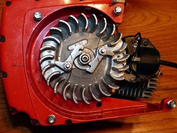 Next comes the reed valve assembly. Here's the parts. 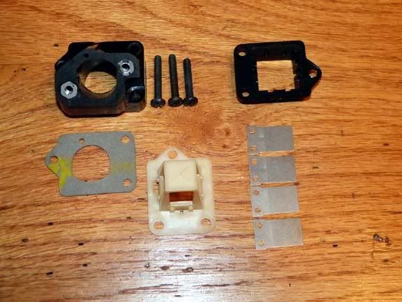 and here's what the opening looks like in the case. 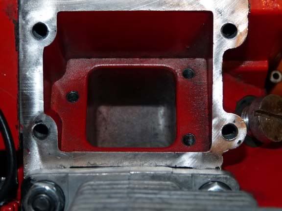 First step is to put in the retainer. All the manuals emphasize to do this first to keep from pinching if you try to put the retainer over the reeds first and put it in as an assembly. 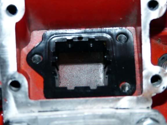 A little oil on on the reed seat and the reeds stick to it very well. 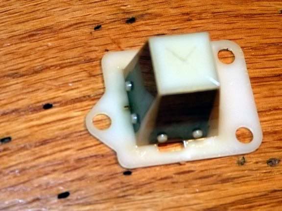 and here it is slid into the retainer. 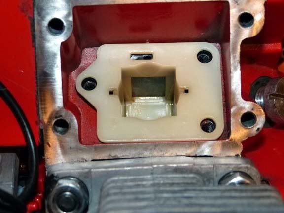 Next comes the gasket and the manifold. The shorter screw goes on the lower right. 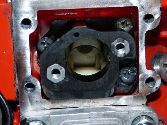 I took a chance reusing the crank seals. Better to do a vac-pressure test just to be sure before going any further. Should have done this before installing the flywheel, but couldn't wait to see if I was getting a spark yesterday. The case needs to be sealed and you need a single access for an air line. Don't forget to put in a spark plug or you'll have a big hole for a leak ;D. Here's the plate for the exhaust. Old inner tubes work good as a gasket, but I used some paper gasket material and applied some grease to help get a good seal. 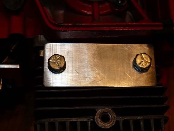 ...and for the manifold. The tap for the lines is on the manifold plate. Reeds don't seal so tightly they have any effect on vacuum here. 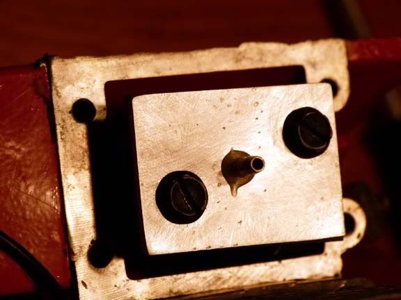 I use a Mityvac for a vacuum source. 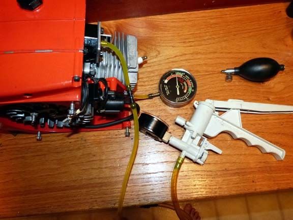 and a blood pressure bulb for pressure. 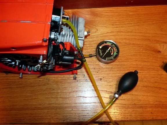 Thankfully, both pressure and vacuum held OK for well over a couple minutes, so no need to yank out the seals for replacement.  |
|
|
|
Post by tribulation138 on Jun 19, 2012 16:06:36 GMT -5
what do use to clean your saw up. I use dish soap??
|
|
|
|
Post by lesorubcheek on Jun 19, 2012 19:55:44 GMT -5
Hi Trib. I use diluted purple stuff (3 parts water, 1 part stuff) usually to get the worst. WD-40 too depending on how oily and sappy. Toothbrushes do a good job of scrubbing without ruining the paint. The cylinder went into the ultrasonic cleaner with diluted purple stuff. Oh, and alcohol does good to dissolve the black rubber goop that old fuel lines, boots, etc. can turn into. The handle assembly is fairly simple, but I'll go through it anyway. Here's the trigger cam and the hi-speed starting latch parts. 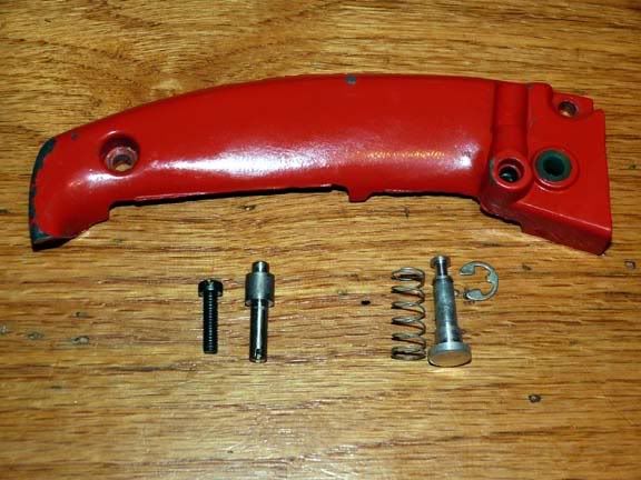 I use a little grease to lube the parts. Here it is assembled. 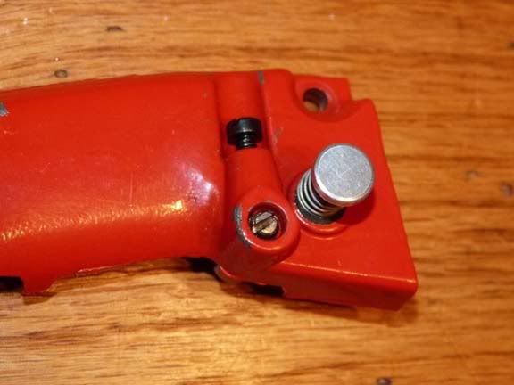 Here's more handle parts including the throttle trigger, bushings, etc. I used some rubber protector on all the rubber parts. Hopefully it'll extend their life for a little while longer. 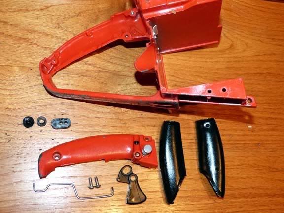 The throttle rod boot is in place and the throttle rod inserted. When the handle is assembled onto the rear handle housing, make sure to line up the throttle rod in the hole in the throttle trigger. Two screws hold it together. 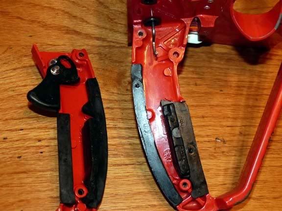 I also installed the kill switch while it was convenient. 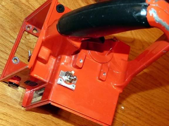 and from the top. 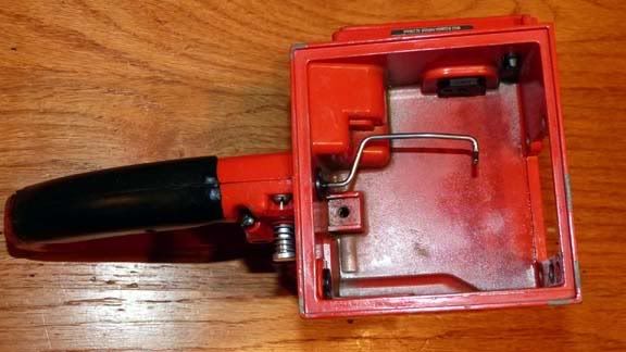 Now its time to join the handle to the crankcase. There's 4 screws in the air box/ carb chamber and one underneath. I messed up in this photo and show 5 all the same length. One needs to be longer. Gasket goes in between. Notice the paper stuffed into the manifold. Never hurts to try to keep things out when the assembly is this far along. 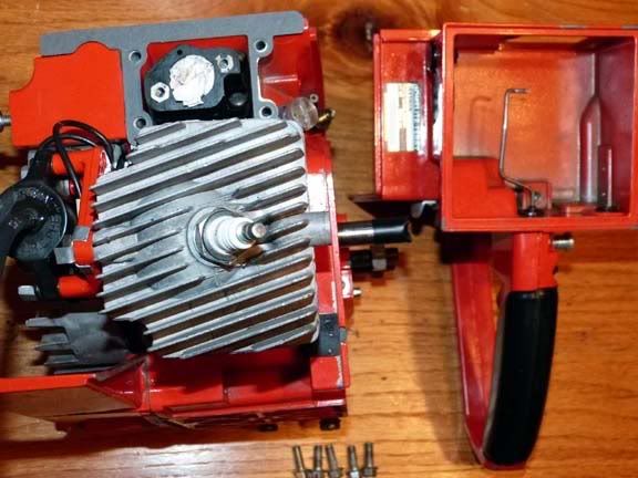 Here's the the screws in the carb chamber. You can see the manifold can get in the way, especially when tightening the lower two screws. A swivel adapter and a ratchet extension make it easy, but if you don't have one, it may be easier to remover the manifold to tighten them and then reinstall the manifold. I really wanted to test the crank seals, so the manifold was installed earlier on. 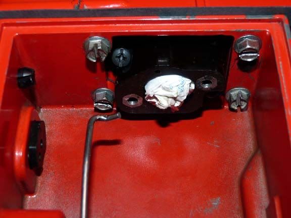 and the one underneath. Note this one is a 80891 12-24 x 7/8 which is a little longer than the 4 in the carb chamber which are 80676 12-24 x 5/8. 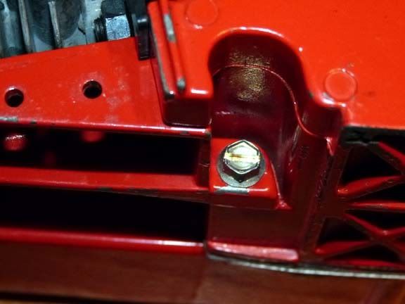 There's two things to do that are a little easier if you do it as you are joining the handle to the crank case. First, the ignition wire needs to feed through a retainer in the upper corner inside the handle. Second, the kill switch wire needs to be connected to the lug on the kill switch. Here's the plug wire as its fed through the retainer bracket. 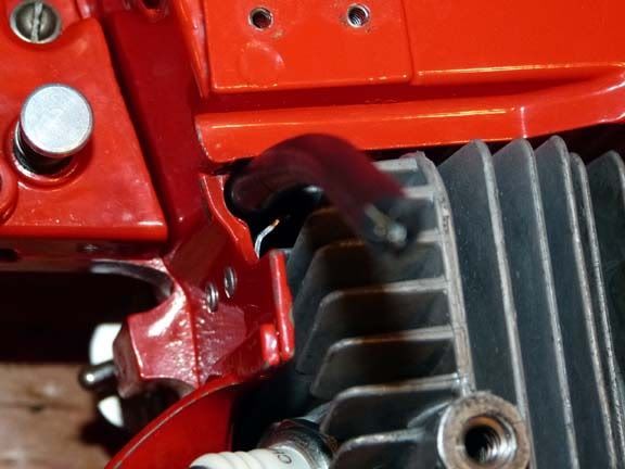 and here's the other side showing the kill switch and you can barely see the inside of the plug wire feeding through. 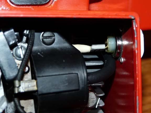 |
|
|
|
Post by lesorubcheek on Jun 20, 2012 18:55:43 GMT -5
I'll try to get some of the oiler parts back together today. Here's some of the parts. The o-rings on the manual oiler are in fine shape, so I'm not going to replace them. 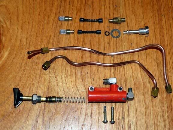 Here's the pickups for the manual and auto oiler that each screw into the case. 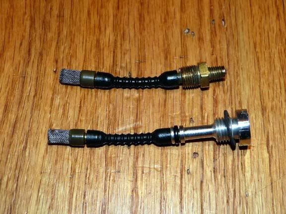 Some oil on the o-ring of the auto oiler pickup is a good idea when installing. Here they are in place. 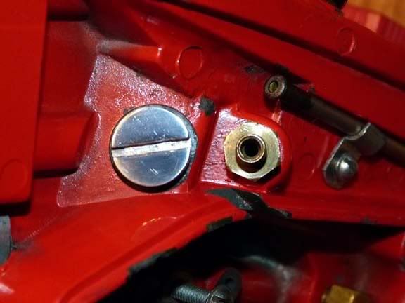 O-rings on the manual oiler also need oil well when putting together. I like to loosely fit the copper lines to the pump and fit it into position as a unit. 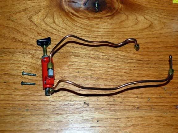 Be careful to get the nuts straight so they don't get cross-threaded. Once all threads have been started, you can tighten all of them down. 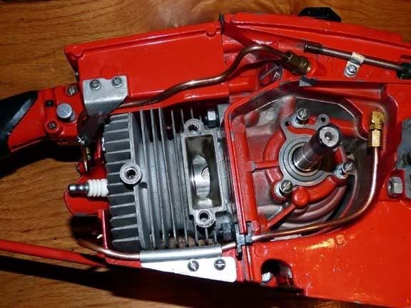 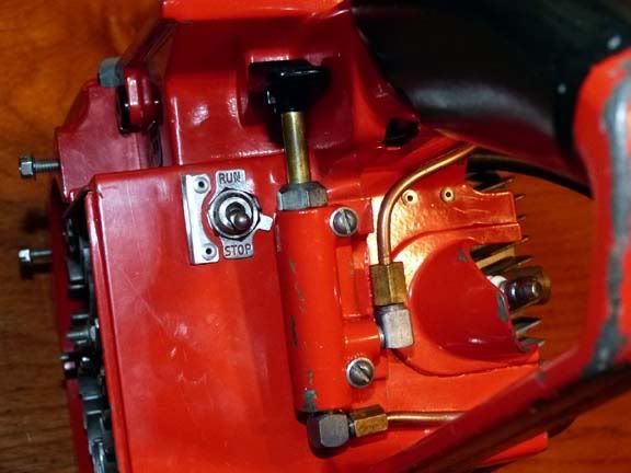 Now for the auto oiler. Here it is disassembled. Wanted to clean it up well before putting it on. Notice the groove on the plunger shaft the rides in the cam screw. This is what causes the plunger to pump. When assembling, oil it well, slide in the plunger shaft, barely screw in the cam screw and hand tighten while at the same time rotating the plunger shaft. Make sure the cam screw slides into the slot on the plunger shaft and doesn't bind on the top. Then put on the bushing on the end and tighten the two small screws. 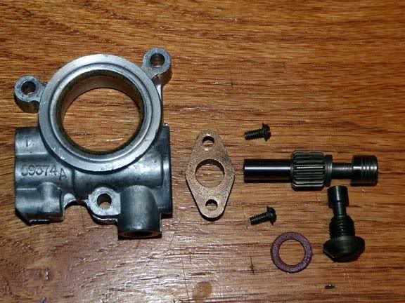 Here's the auto oiler assembled and ready to install. 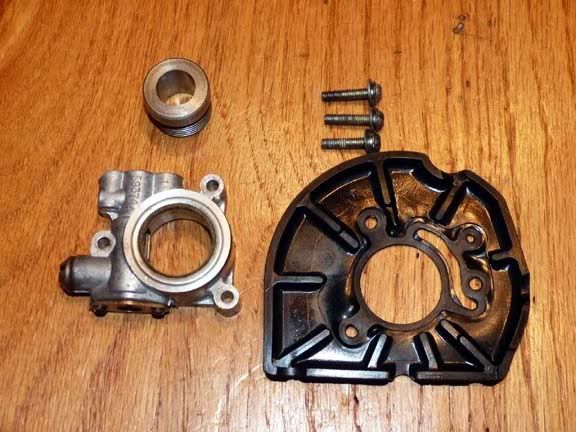 Its a good idea to use some silicone around the edges of the plastic seal plate to help sawdust particles from getting by and causing buildup around the cylinder. You can guess.... still no silicone in the house. I fit the parts so you can see how they look, but I'll take it loose and seal around the edges before I finish up. 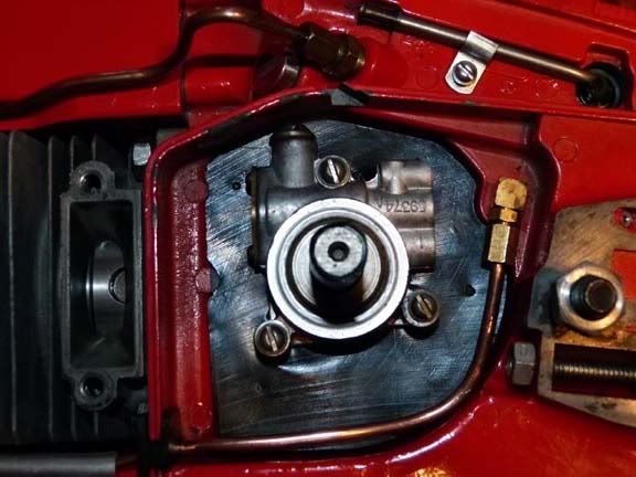 |
|
|
|
Post by Brian VT on Jun 20, 2012 20:03:26 GMT -5
This is fantastic work. How many times can we say "Thank You" ?
|
|
|
|
Post by lesorubcheek on Jun 20, 2012 21:20:45 GMT -5
No need to thank me Brian. Its fun to share... just wish there was more time in the day. Can't wait to see your project in progress! The more 925s running in the universe, the better the place will be!
Dan
|
|
|
|
Post by Brian VT on Jun 20, 2012 21:42:22 GMT -5
Can't wait to see your project in progress! Dan I wish I could say that it will be soon. It seems that everyone in a 25 mile radius knows that I like to mess with old chainsaws. I have a few I need to get to. I should turn most of them away, but you never know when something extraordinary might show up so I just smile and tell them that it might be a while and how I mostly like old Homelites. Now that the summer heat is here I won't mind spending time in the shop and maybe I'll bang a few of these out. I'll try to follow your lead and document anything that might be of interest to folks here. |
|
|
|
Post by lesorubcheek on Jun 21, 2012 20:26:13 GMT -5
You're lucky Brian. I fix up a few mowers, trimmers and blowers for people, but hardly anybody I know is into chainsaws like myself. With your connections, you're bound to come across some nice, fun saws. Thought I'd go through the starter today. I had already put it together to test the ignition a couple days ago, but its nothing to go through it again with some pics. Here's the parts. 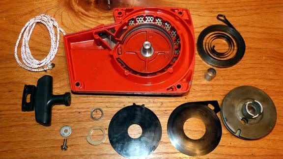 First, lay in the inner shield. 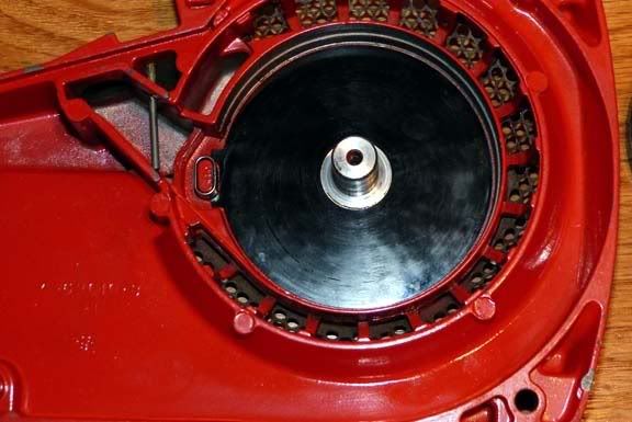 Then the spring. Notice the spring fits around a bushing that sits on the tab of the housing. The bushings helps prevent the spring from wearing away the much softer magnesium. 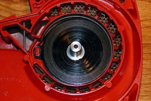 Next, spring lock bushing goes over the post. 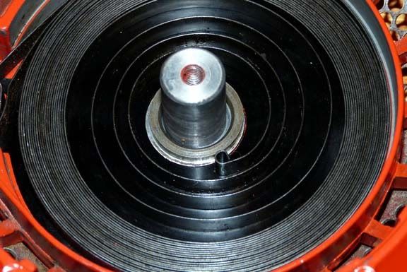 Then the rewind spring lock sits on top of the bushing. The bushing with the lock make it easy to align the pulley. 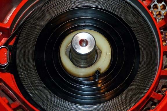 The post bushing slides over the post. I use a little bearing grease around it for lubrication. 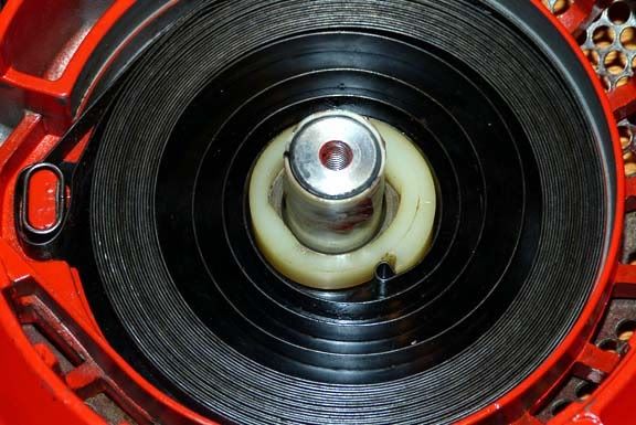 The outer spring shield sits over the starter spring. 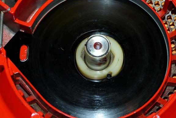 Time to wind the starter cord onto the pulley. I use a butane lighter to heat the ends of the cord after cutting to keep them from fraying. Tie a knot on one end and run the other through the pulley. 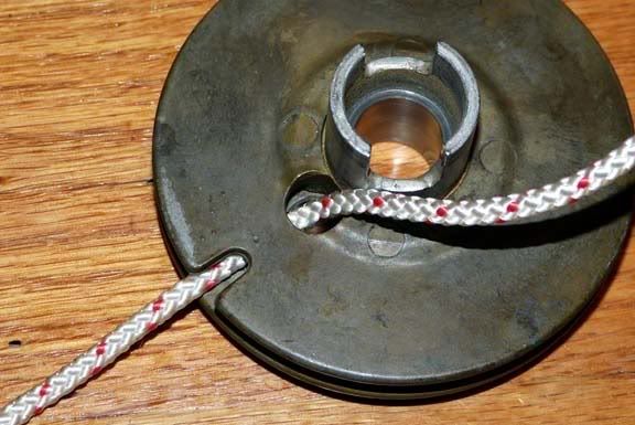 Pull the cord all the way through until the knot is snug inside the cutout hole in the pulley. Then wind the cord clockwise. 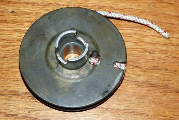 Sit the pulley on the post feeding the cord as shown. 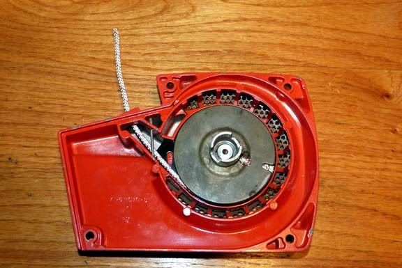 Put on the washer and screw and tighten it so the pulley is secured. 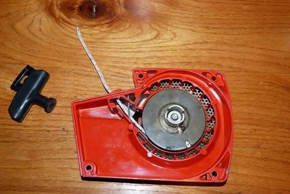 Run the cord through the base of the starter grip and through the retainer. Tie off the end with a knot and pull it snug. Leave the cord slack by several inches. Feed the cord through the cutout on the edge of the pulley and pull it up enough it can rotate around the center. Rotate the pulley clockwise about 2-3 times depending on how much slack in the cord. This will tension the spring so it'll retract the cord completely. A video here would help I think, but once you figure it out, its easy. 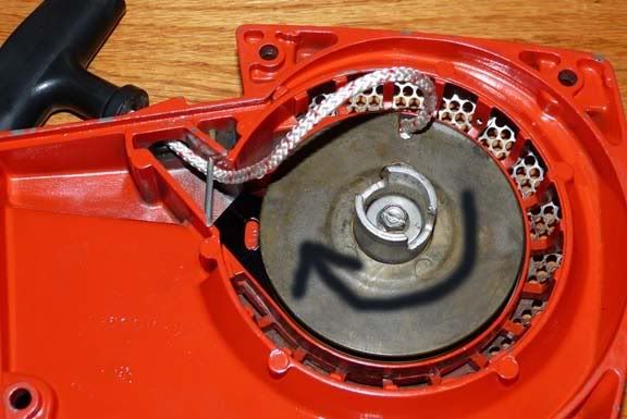 Pull the cord through by the grip and you're done. 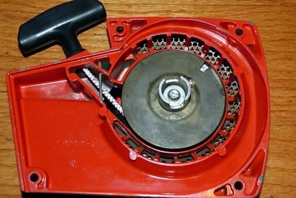 |
|
|
|
Post by tribulation138 on Jun 22, 2012 5:51:39 GMT -5
great work. this is my passion with old chainsaws. cleaning and rebuilding whats necessary. some people just collect piles of chainsaws and never even get a chance to dive in to them or even pull the rope.
|
|
|
|
Post by lesorubcheek on Jun 24, 2012 20:31:12 GMT -5
I hear ya Trib. Little can compare with the joy of that first pop after you've got one of these back together. Finally got some sealer for the shield under the auto oiler, so now the clutch can go on. Here's the parts. 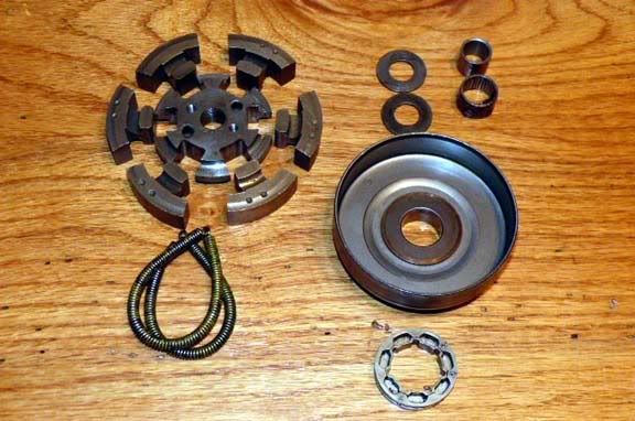 Here's how I put these together. Start with the spider and roll one of the springs on one side. 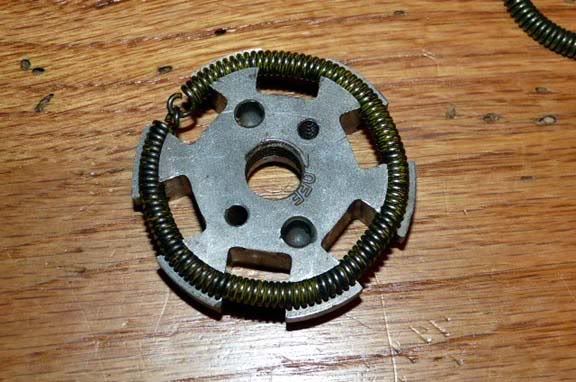 Next, slip in the shoes. Slide them underneath the spring and roll them up into position. 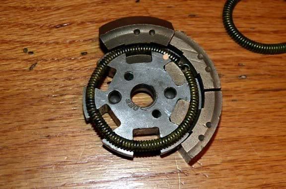 Here they are all in place with the single spring. 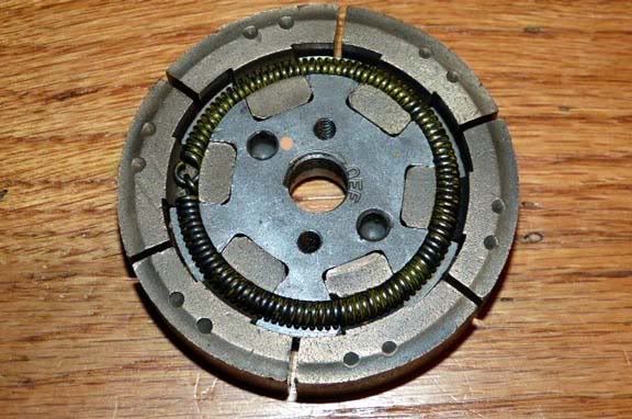 Next its time for the second spring. It takes a little force, but it can be rolled into the groove stretching as you go until it snaps down into place. 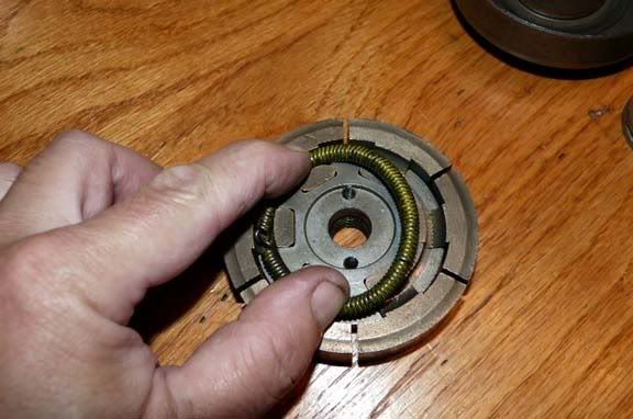 and here it is ready to go. 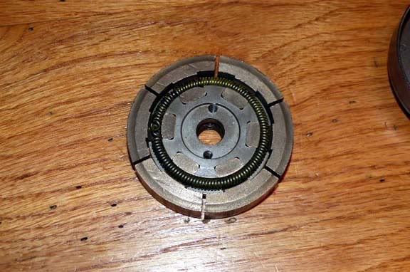 A thrust washer goes on the crank first. 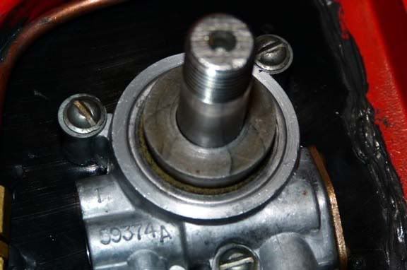 Greased up the roller bearing with plenty of bearing grease. 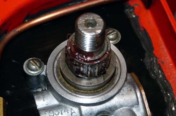 The splined hub with its sprocket in place go over the bearing. A second thrust washer goes over the crank. 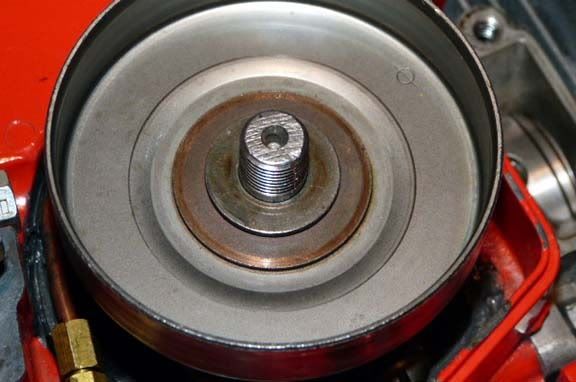 Its important to not have the starter cover on when its time to tighten down the clutch. The dogs of the starter can engage since you tighten the clutch counterclockwise. Use the rope trick to hold the piston and tighten down using a clutch tool (the Homelite tool is nice, but you can make one with some metal dowels and a piece of metal). 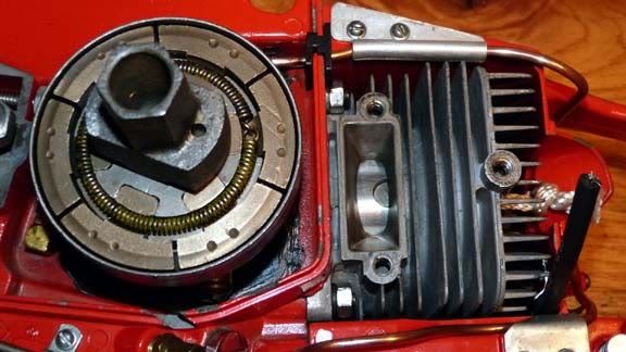 Finally install the cover. I had some belleville washers, so thought they wouldn't hurt. 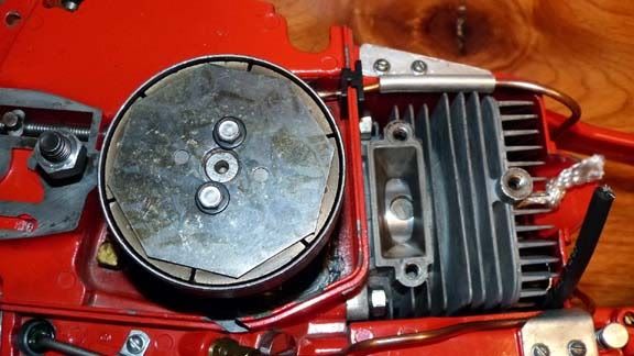 Now the starter cover can go on.  Exhaust will be next. Here's the parts. Decided to leave off the spark screen, but may put one on later. 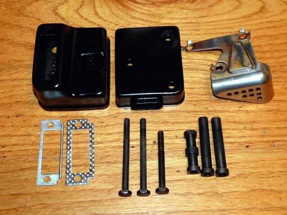 Slide the re-enforcement plate inside the muffler base where the bolts go through. The support spacers go in next. 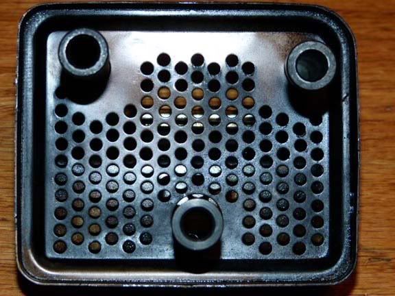 Sit the top cover on, the chrome shield in position and insert the 3 bolts. 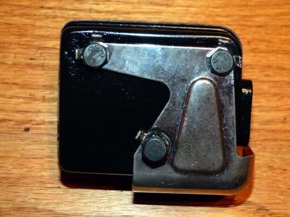 Don't forget the muffler gasket between the muffler and the cylinder. 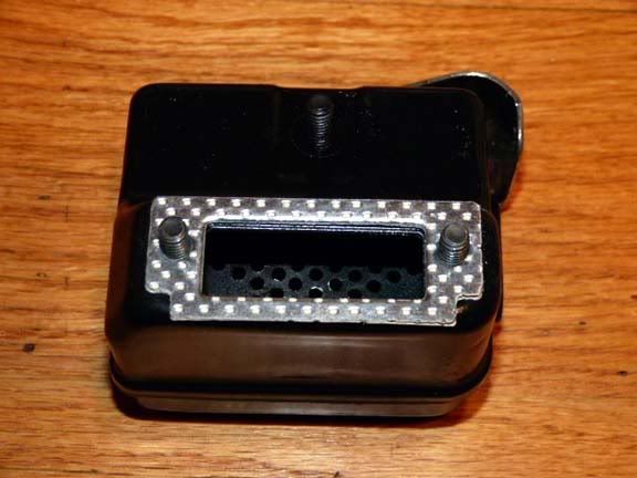 Tighten it down and bend the locking tabs to keep the bolts from loosening. 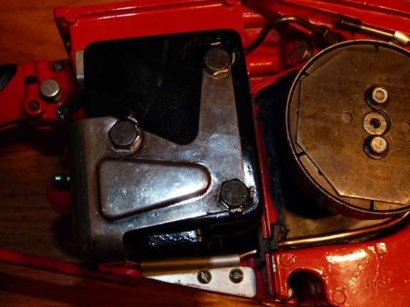 |
|
|
|
Post by lesorubcheek on Jun 26, 2012 20:12:02 GMT -5
Thought about taking pics of the carb rebuild, but its not that different than other 2-stroke saw carbs, so I decided to skip. Here's the carb ready to install. 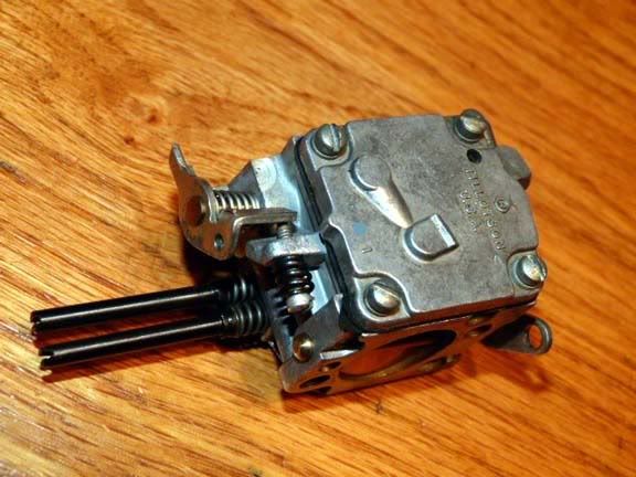 One thing that is a little different with the 925 carb is the governor. I tried to unscrew it to show the inside, but it was very stubborn. After a slipping screwdriver, I decided to leave it alone. This governor can cause problems if it fails, and usually it results in running too rich on the high end and not being able to lean it out enough to run properly. The solution is to put a plug in it to eliminate it. I hope this one's going to work, because removing it will not be fun. You can see it just ahead of the choke lever. 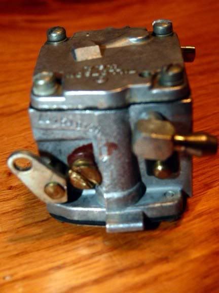 You can use the factory fuel line (left), or another grommet and tygon or whatever you like. I prefer the clear line to see the fuel. 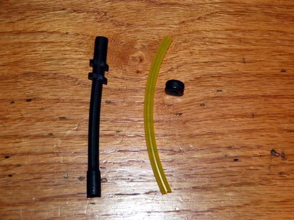 Install the grommet in the hole in the chamber. 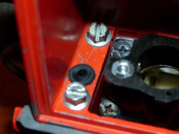 And here's the best way I've found to install the carb. First, fit the fuel line onto the carb. It has a fairly large fitting and is difficult to get on unless you do it in the open. 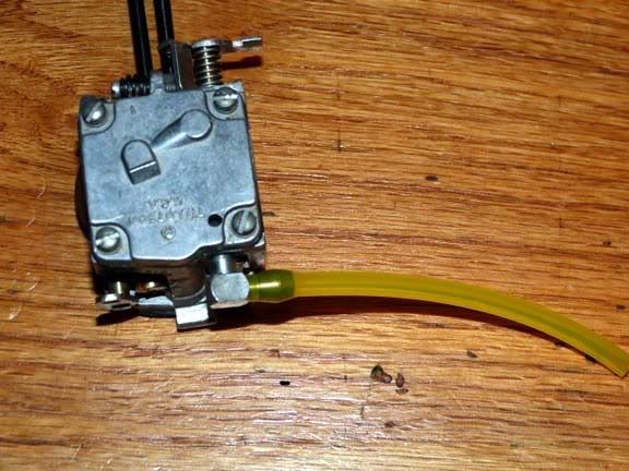 Then feed the other end of the line through the grommet. You can cut this end at an angle to make it easier to grab, and a little light oil helps it to slide through. Grab and pull it through. 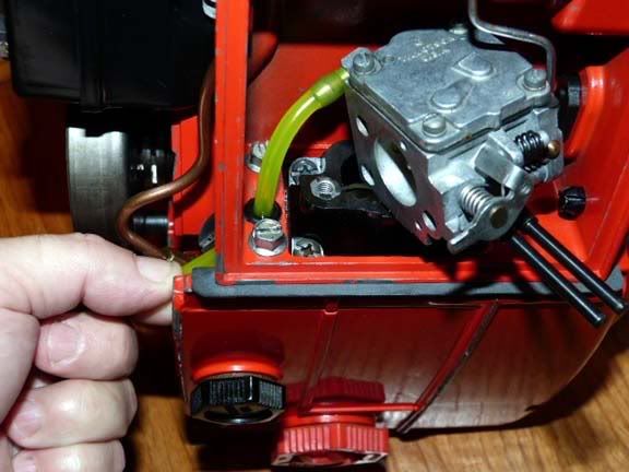 Before pulling all the way, twist and connect the throttle linkage and insert the lo-hi needle screws into the openings in the grommet on the side. You'll need to get the two carb bolts and the gasket between the carb and manifold into place also while you can tilt it around. 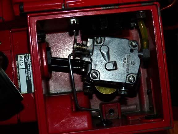 Gradually pull it all the way and slide the end of the fuel line onto the metal 90 degree tube. Now you can secure the clamp that holds the tube in place. Also tighten the two carb bolts. 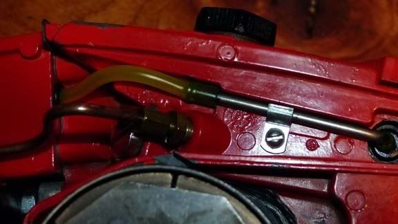 Choke linkage is pretty simple. Only problem is those little brass split cotter pins aren't that easy to find. I try to reserve my supply for the nicer saws, so for work saws like this, I cut a piece of stainless wire. The cotter pins are 1/32" x 1/2" long. Somebody has to have these, but I've had little luck with places like McMaster Carr, etc. 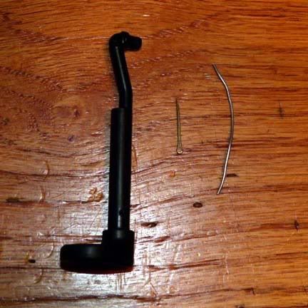 Choke linkage in place and the air filter mount with the carb baffle cover installed with a single bolt. 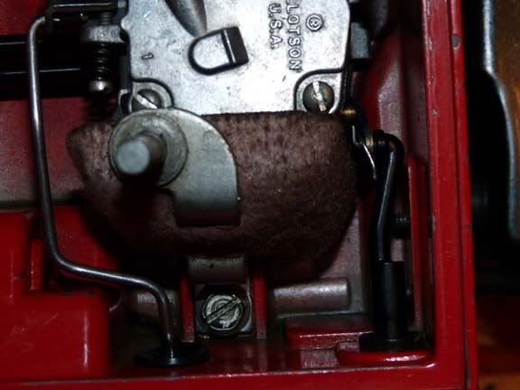 Put on an air filter and then the cover. 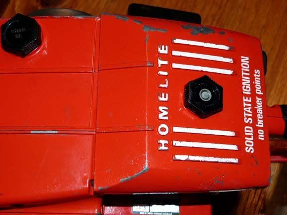 |
|