|
|
Post by lesorubcheek on Jul 11, 2020 21:45:19 GMT -5
Now for the rear handle. Had to decide whether to use a NOS one, repaint, or just use the original. After a lot of thinking about the fuel tank, and decision with it, I decided to just use the original handle as is. Here's all the parts cleaned and laid out for assembly. Using one of the Stihl 066 throttle rod boots.  Ready to go. The IPLs show the bolts on the decomp lever late facing up with the nuts inside the carb chamber area. This tends to interfere with the felt and cotter pin for the weep hole, so I always put the bolts facing down.   Here's the insulating spacer, gaskets and the filler block.  The filler block sits on tabs in the crankcase. These were added on the first generation 2100. The 2000 and Super 2000 didn't have the filler block. Never read why it was introduced. It limits the travel of the reeds, so maybe there was a reed breakage problem on the 2000??? It also slightly decreases crankcase volume which would increase fuel/air velocity, but certainly no idea if this had anything to do with why they were added. If anyone has any idea, it'd be great to find out why it was added. 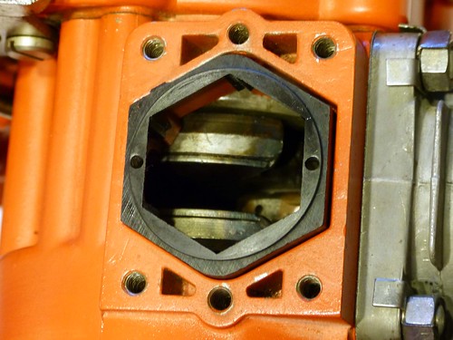 Sit a gasket, then the spacer, and then the second gasket in place.  Slip the decomp lever into the decomp valve and sit the handle into position. Secure it with the 4 bolts. |
|
|
|
Post by lesorubcheek on Jul 11, 2020 22:23:47 GMT -5
With the rear handle in place, the fuel tank needs to go on next. Here's the area where it sits.  and... before the tank goes on, need to get the chain guard in place. Loosely secure two bolts to hold it in place.  Now for the fuel tank and a little problem that's bugged me ever since I tore the saw down. I really wanted to put on a new tank, but there's a couple oddities with the new tanks even though they have the same A-67739 part number the 3100 IPL shows.  The new tanks all have a re-enforced rib above the outer attachment tab. Also, not shown here, but there's no hole threaded underneath to attach the third bolt for the chain guard to the tank. Here's the original 3100 tank showing the area being talked about. The tab without the re-enforced area is like the 1100 and earliest 1130 tanks. So, you may think why not just use a A-63399 tank from one of them? The problem here is they used #6 screws to join the tank. The 3100 and newer style tanks used 8-32 screws to join the tank. So, it remains a mystery why the 3100 tank has the same part number as the newer style tanks, yet doesn't have the re-enforcement and does have the hole tapped underneath for the chain guard attachment. Maybe some later 3100s used the A-67739 and this one happens to have been made before the change.... who knows.  Anyway, with all this confusion over the tank, I decided to use the original. Also decided not to paint it. It's not that shabby so decided to just use as is. I know this all sounds pretty stupid and excessive, but as said before, I'm probably not gonna lay hands on another one of these. This is how the tank looks on the inside. No sign of a part number. It may be under the screen, but I don't want to remove it to find out. There are traces of magnesium corrosion, so soaking it good with Gibbs.
Here's the fuel fitting with gasket and o-ring, hose and filter.  It's easier to install the fitting with the cover off, even though you can work through the filler hole pretty easily too. Since it's apart anyway, here's how it looks.  Here's the tank buttoned up ready to install.  |
|
|
|
Post by lesorubcheek on Jul 11, 2020 22:36:34 GMT -5
Attach the fuel hose to the tank.  Slide the fuel line through the handle, slightly raising the drivecase side of the tank until it clears behind the attachment point, then lower it into position. Loosely attach the 3 tank screws.  There's 2 screws on the drive side securing the tank.  One more screw on the facing where the start cover attaches. Also time to install the third chain guard screw under the tank (the hole missing on the newer tanks) and tighten everything up.  |
|
|
|
Post by lesorubcheek on Jul 11, 2020 23:04:15 GMT -5
Now for the reeds.    The 2000 used six 63166 reeds. Starting with the Super 2000, they used five 63166 and one 67107 split reed and the HL-273A carb. There's 2 passageways to the carb. One has the normal impulse of vacuum and pressure, but with the split reed, the second passage only provides a vacuum. You can see the opening on the face of the carb.  I've never heard anyone explain the purpose of the vacuum-only port, nor found anything in any manuals. If anyone knows how this works on the HL-273A, it'd be great to learn what's really going on. I'm not going through the carb rebuild since it's been done numerous times. I find it's easiest to install the carb already fitted to the manifold, so here's the parts ready to go together.  Fit the reed cage with a gasket into the handle with the openings facing the rear.  I like to use a little gasket cement on the cork gasket and fit it in position on the intake manifold. This helps make sure the passageway holes are aligned.  Here's the handle ready for the carb.  I slide the fuel hose onto the carb first, then attach the throttle lever, align the Hi/Lo needles into the grommets on the side and slide it left. Finally, tighten the two screws that attach the manifold, attach the rear carb support and the choke lever. |
|
|
|
Post by xl130 on Jul 12, 2020 8:09:21 GMT -5
Great step by step pictures and explanation! I’ve only had a few of the standard and more common saws apart. It’s really interesting to see the full breakdown on a rare saw like this. Very cool! Thanks for sharing. Looking forward to seeing the final results.
|
|
|
|
Post by edju1958 on Jul 12, 2020 9:24:04 GMT -5
Unfortunately the closest I'll ever get to a 3100 are these pics.The bigger muscle saws from Homelite weren't that prevalent in my area.
|
|
|
|
Post by lesorubcheek on Jul 12, 2020 13:13:54 GMT -5
Great step by step pictures and explanation! I’ve only had a few of the standard and more common saws apart. It’s really interesting to see the full breakdown on a rare saw like this. Very cool! Thanks for sharing. Looking forward to seeing the final results. Thank you very much! It's a great feeling to know someone is enjoying the thread. Back around 20 years ago when I went saw crazy, about the only saws I knew about were a David Bradley, Homelite 350 and a Poulan 285. These were my Dad's saws. Had no idea about Homelites of the past. Finding Arboristsite opened so many doors to learning about all the awesome saws Homelite had made over time. When HoH was founded, well, it was even better! It's been a steady addiction ever since, just hard to find enough time. Always enjoyed a saw build thread, or any saw discussion for that matter, and feel that sharing what we've learned over time is not only a joy but an obligation. It's just a shame that so many of these saws are getting almost impossible to find. Dan |
|
|
|
Post by lesorubcheek on Jul 12, 2020 13:20:43 GMT -5
Unfortunately the closest I'll ever get to a 3100 are these pics.The bigger muscle saws from Homelite weren't that prevalent in my area. Ed, you never know. I felt the same way. Around this area of South Alabama, North Florida, I don't see too many either. About the only bigger local saw I ever found was a Stihl 070 on craigslist. Practically all of my bigger saws were either from forum members or feebay. Thing is you just never know what opportunities will pop up and when. Dan |
|
|
|
Post by edju1958 on Jul 12, 2020 18:31:24 GMT -5
You're probably right Dan.I do have an XP-1000 that I've had for a couple of yrs.now.I just gotta get "in the mood" to start tearing into it & do a rebuild.I did pick up another half of a XP-1000 for parts as well.Right now I'm having too much fun with the smaller saws of all brands.
|
|
|
|
Post by lesorubcheek on Jul 13, 2020 16:14:13 GMT -5
Ed, I hear you. I think one of my favorite saws to tear into are 150s. Most people hate 'em, and I did to start with too. I think it was one of those things where I was determined not to let it win the battle and then after doing a few, it kinda grew on me. One thing for sure, I'm alot more likely to grab a 150 or SEZ than this 3100, because there ain't many trees around here that need it.
Dan
|
|
|
|
Post by lesorubcheek on Jul 13, 2020 16:48:41 GMT -5
For the ignition, first thing is to make sure points are clean and the surfaces contact and the condensor is in good shape. Up until a few years ago, all I had to test a condensor was my multimeter which has capacitance measurement. After a really trying experience with a David Bradley condensor, decided to make one of the condensor testors diagrammed in some Homelite literature. I can't find the page, but it's entioned somewhere here on HoH, at least I think so. Sure enough, the first condensor I tested showed that it leaked.  The tester uses 2 button. The left to test charging the condensor and the right to test discharging it. It uses neon lamps for indicators. The charge lamp should only flicker once after pressing and holding the charge button. After releasing and waiting a few seconds, the discharge lamp should blink once when the discharge button is pressed. The first condensor I tested would not hold it's charge for more than a second or so. The second worked fine. Both show a little or 0.2 microfarads though on the capacitance meter. One of these days I want to make a video walking through the electronics of the tester.  Here's the ignition parts laid out and cleaned. I use alcohol to wipe everything clean. I also added a little lube inside the points where they pivot. There's a small clip with a washer under so you can separate the points.  Here's the points in the breaker box and the condensor in place.  The metal spacer washer goes on first.  Then the felt washer.  and then the breaker box goes into place.  I apply a little of this cam lube on the crankshaft where it contacts the points. It's made specifically for breaker point ignitions.  The next thing to do is to set the breaker point gap. I always wipe the feeler gauge with alcohol to make sure no grease gets on the contact surface. After the gap is set, time to put on the cover with gasket underneath, slip on the retainer and tighten the retainer where the condensor sits. This particulat cover has another felt washer glued to the top. I don't think this was standard, but then I've seen more than one cover that had on attached. Anyway, I left it in place since it may help keep the insides cleaner. 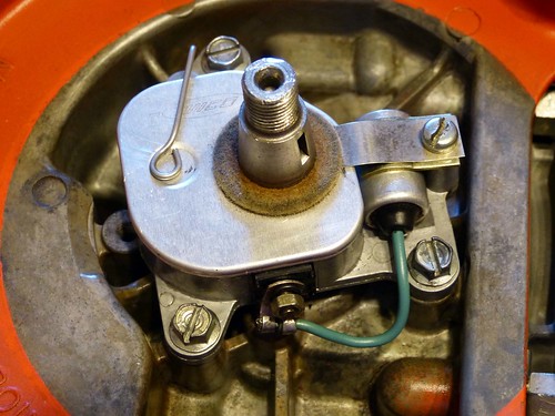 |
|
|
|
Post by lesorubcheek on Jul 13, 2020 17:07:39 GMT -5
The coil goes on next. The lead from the coil to the breaker box goes through a small opening in the case. It fit better on the terminal block being inside the condenser lead so that's the order they were fitted. Also don't forget to attach the lead that goes to the kill switch. I slid the coil as far back as it would go and snugged a couple screws to hold it in place. 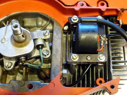 Flywheel goes next. Here's the parts.  The original flywheel to this saw had one broken cooling fin, so I swapped for a good one. For some reason I've came across several 2100s with a broken fin. I guess people just didn't know about using the rope in the plug hole trick or something. Anyway, with the flywheel on, torque it to 250 in-lbs.  I use old business cards to set the gap between the flywheel and coil core.  Finally, I put a plug on with the base resting against the cylinder head and did a hand spin spark test. Seeing a spark, I think it's good to go. |
|
|
|
Post by edju1958 on Jul 13, 2020 17:48:19 GMT -5
The homemade capitence tester for condensers has caught my attention.I've been trying to get the point across that a condenser can test "good" on a multimeter,but leak like crazy.Right now when I get a bunch of condensers that I question (which is most of them) I send them to a guy in Maryland,N.Y.who tests them for me free of charge.He just turned 80 in Feb.,so I don't think he'll be doing it much longer.
|
|
|
|
Post by lesorubcheek on Jul 13, 2020 19:18:52 GMT -5
Ed, you're absolutely right. These things really need to be tested to verify they can hold a charge. Had a David Bradley that wouldn't run worth a flip. I tried everything. The condensor looked fine when measuring it's capacitance using a meter. I finally decided to change it out just to see, and sure enough it ran great afterwards. That was enough to convince me that they really need to be tested in a way other than just measuring capacitance. Wish I had something like a Merc-O-Tronic, but haven't found one yet that's been affordable. I had seen the Homelite schematic in a dealer package. When Undee70ss posted the link, it sparked interest again. I finally found the link to the post. houseofhomelite.proboards.com/thread/5821/homelite-condenser-testerI never understood neon lamps before playing with this. They act as an open circuit (infinite resistance) until they fire. They fire when the appropriate voltage exists across them. I think these were somewhere around 70 volts. Once they fire, they act as a short circuit. So the way the tester works is, when you apply the charge, current flows until the condensor is charged. As this current flows through the resistor across the bulb, voltage is created and will fire the lamp. The capacitor will charge within a second or less, so you'll only see one flash. If the condensor holds charge, no more current will flow and the lamp will stay off after the one blink. If it flickers, that means it's rapidly discharging and recharging. So with the condensor charged, when you press the other button, the condensor will rapidly discharge, causing current to flow across the other resistor and fire the other lamp. It took me awhile to understand how this works, and it's key to understand how neon bulbs work. Dan |
|
|
|
Post by edju1958 on Jul 13, 2020 23:02:47 GMT -5
I know what you mean about the Merc-O-Tromic being affordable.I did a little research on them a few months ago.The guy who I send my condensers to to have tested uses a Graham tester,it works juist like the homemade one you have does with the blinking neon lights.He showed it to me last yr.when I went for a visit & had my condensers tested. I'm not that keen or literate on electronic devices being made by myself,or even how to operate them.I have a hard enough time with turning on my computer.Lol
|
|
|
|
Post by lesorubcheek on Jul 20, 2020 21:51:37 GMT -5
Working on the starter next. Thought I'd start out showing a handy gadget for cutting starter rope. People over at arboristsite talked about these years ago. Do a search for "weller solder rope cutter". They cut cleanly and don't leave any fraying on the ends.  To measure how much rope to use, I wind the starter pulley until it's full and leave enough extra to run through the cover and have a knot on both ends. Used #6 rope. Rope sizes are based on 32nds, so #6 is 6/32 or 3/16". After rope is cut, run one end through the hole in the starter pulley and push it out and tie a knot. Press the knot down so it's flush so it won't interfere with the sawdust shield after assembly.  Here's the parts.  Decided to use the original starter cover for a couple of reasons. First, even though the decal is rough, it IS the original part. Secondly, according to the IPL and what was on this saw, it uses A-64178-3. All the new replacement ones I have are A-64178-3A. The A-64178-3 doesn't have the nylon starter post bushing where the A-64178-3A does. It's nicer with the bushing, but not original. Looks like these were introduced on the Super 2100.  The inner spring shield goes into the cover and sits with the smaller notch to the left of the post for the rewind spring.  Put in the spring next. I apply a very small amount of gibbs and wipe it for corrosion prevention.  Drop in the spring lock with the tang facing so it engages the end of the spring. Then drop in the outer spring shield.  I use some oil free lubricant for guns to lube the post, then run some rope through the cover and drop the pulley onto the cover post. Secure the pulley with washer and bolt. Finally attach the starter grip as shown.  |
|
|
|
Post by lesorubcheek on Jul 20, 2020 22:07:51 GMT -5
Push the insert into the grip and, just as xl130 showed in his video houseofhomelite.proboards.com/thread/9621/slack-starter-rope-fix, take the slack out of the rope.  And this is how it will look.  Here's the pieces ready to attach to the saw.  The screen goes onto the fan housing first, then the sawdust shield, and then the assembled starter cover. Attach the 3 bolts. Here's a view from inside.  Pull some rope out with the grip, sit the housing into position and slowly release the grip letting the pulley rotate and sit into place within the pawls. Here it is in place.  And to wrap up for today, I'll go ahead and put on the lower handle brace.  Here's from the side. I'd also left out the bolt that secures the handle to the crankcase, so it's now in place.  |
|
|
|
Post by lesorubcheek on Jul 21, 2020 17:43:14 GMT -5
Now for the exhaust. First, an interesting item regarding the muffler baffle. The 2000, Super 2000, 2100, 2100S (Standard) and the 3100 all used 65459 (shown left) for the baffle. However 2100 Supers used 65459-A (shown right). This is according to their IPLs.  The 65459 has 32 holes (there's 34 total but 2 are for the studs) where the 65459-A only has 25. You'd think that the thin ringed Super would be the one with a more open exhaust, but it's not the case. Maybe Homelite felt the thin rings needed to be detuned a bit to avoid overheating. It could be related to use of the downdraft muffler which was on most 2100 Supers, but truth is the early 2100 Supers could come with both types of muffler caps. The reason for this may be described in a TSB somewhere, and it'd be nice to know why they did it. Another minor muffler difference was in the muffler body.
On the left is A-65458-1A which was used on the 2100 Super, and on the right is A-65458-1 used on the others. Notice on the -1A the metal plate added. With these, the short outer studs actually helped hold on the muffler body. On the -1, all 4 studs could be installed and the muffler then slid on. Same goes for removal, the short studs had to be removed to pull off the muffler body on the -1A, but not on the -1. Homelite also sold the muffler stud kit A-69215 that included the plate. This could be added to earlier mufflers if you prefer the extra holding it provided. Again, there may be a TSB describing this, but I don't know it.
 The 3100 IPL shows the option for the downdraft quiet muffler kit A-67689.  It may be interesting to hear the difference, but for now the original muffler is gonna be used. |
|
|
|
Post by lesorubcheek on Jul 21, 2020 18:02:36 GMT -5
To install the studs, I just use double nuts, tightened on each.  Since I'm using the original muffler, all four studs are installed.  Then the muffler body just slides over the studs.  Next comes the baffle.  Not putting a spark arrester screen, just put the cap, fit the lock tabs and then install the nuts. Tighten and bend the lock tabs to hold the nuts in place.  Muffler shield is held on with three bolts.  Finally slide in the cylinder shield. I'm actually using one with the O-ring on the shield mounting screw. The O-ring wasn't used on 3100s, at least not according to the IPL, but hey, I'll take it off if someone really feels it's not proper.  It's easier to install the shield with the decomp clamps removed and then put them on after it's in place. The clamps need to be aligned anyway after the shield is in place. |
|
|
|
Post by lesorubcheek on Aug 12, 2020 14:31:33 GMT -5
Been a little busy, but finally did a little more on the saw. Here's the inside of the gear housing cover. Bearing feels nice and tight, so not gonna change it.  Here's the outside of the cover with gasket, bolts, weep hole plug and oil filler cap.  Before installing the cover, I lightly oiled the gears and did a short video showing how they move.  3100 gears 3100 gears by J H, on Flickr I used a block of wood to seat the cover on the bearing and then tightened the bolts.  The front handle bar was a little dinged on it, so dug around and found one in better shape.  The holes were TIGHT on the new handle bar, but finally persuaded the bolts through.    |
|